The function of the intake structure, whether it be an open channel, a fully wetted tunnel, a sump, or a tank, is to supply an evenly distributed flow to the pump suction. An uneven distribution of flow, characterized by strong local currents, can result in formation of surface or submerged vortices and with certain low values of submergence, may introduce air Into the pump, causing a reduction of capacity, an increase in vibration and additional noise. Uneven flow distribution can also increase or decrease the power consumption with a change in total developed head. The ideal approach is a straight channel coming directly to the pump or suction pipe. Turns and obstructions are detrimental, since they may cause eddy currents and tend to initiate deep-cored vortices.
The amount of submergence available is only one factor affecting vortex-free operation. it is possible to have adequate submergence and still have submerged vortices that may have an adverse effect on pump operation. Successful, vortex-free operation will depend greatly on the approach upstream of the sump.
Complete analysis of Intake structures can only be accurately accomplished by scale model tests. Model testing is especially recommended for larger pumping units.
GENERAL DATA INFORMATION
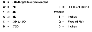
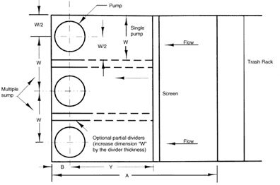
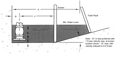
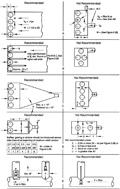
Subject to the qualifications of the foregoing statements, Figures 7 through 10 have been constructed for single and multiple intake arrangements to provide guidelines for basic sump dimensions.

Fig. 7 Sump dimensions

Fig. 8 Sump dimensions, Plain view, wet pit type pumps

Fig. 9 Sump dimensions, elevation view, wet pit type pumps

Fig. 10 Mulitple pump installations
All of the dimensions In Figures 7 through 10 are based on the rated capacity of the pump. If operation at an increased capacity is to be undertaken for extended periods of time, the maximum capacity should be used for obtaining sump dimensions.
If the position of the back wall is determined structurally, dimension B in Figures 7 to 10 may become excessive and a false back wall should be installed.


