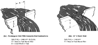
Fig. 6 Weirs
A weir is particularly well suited to measuring flows in open conduits and can be adapted to extremely large capacity systems. For best accuracy, a weir should be calibrated in place. However, when this is impractical, there are formulas which can be used for the various weir configurations. The most common types are the rectangular contracted weir and the 90 V-notch weir. These are shown in Fig. 6 with the applicable flow formulas.
g.) Pitot tube
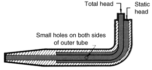
A pilot tube measures fluid velocity. A small tube placed in the flow stream gives two pressure readings: one receiving the full impact of the flowing stream reads static head + velocity head, and the other reads the static head only (Fig. 7). The difference between the two readings is the velocity head. The velocity and the flow are then determined from the following well known formulas.
Since the velocity varies across the pipe, it is necessary to obtain a velocity profile to determine the average velocity. This involves some error, but when properly applied a calibrated pilot tube is within plus or minus 2% accuracy.

Fig. 7 Pitot Tube


