Predictive and Preventive Maintenance Section 3

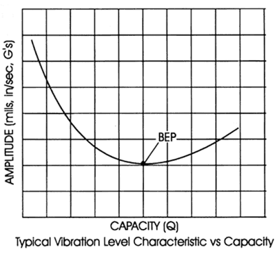
Typically, readings are taken on the motor outboard and inboard bearing housings in the vertical and horizontal directions and on the pump outboard and inboard bearing housings in the vertical and horizontal directions. Additionally, an axial vibration measurement is taken on the pump. The inboard location is defined as the coupling end of the machine. it is critical that when the baseline vibration measurement is taken that the operating point of the pump is also recorded. The vibration level of a pump is directly related to where it is operating and in relation to its Best Efficiency Point (BEP). The further away from the BEP, the higher the vibrations will be. See the following chart for a graphical representation of vibration amplitude- vs- flow.

sect i11 fig1
The engineer must also look at the frequency where the amplitude is occurring. Frequency identifies what the defect is that is causing the problem, and the amplitude is an indication of the severity of the problem. These are general guidelines and do not cover every situation. The spectrum in the chart is a typical spectrum for a pump that has an unbalance condition. Bearing defect analysis is another useful tool that can be used in many condition monitoring programs. Each component of a roller bearing has its own unique defect frequency. Vibration equipment available today enables the engineer to isolate the unique bearing defects and determine if the bearing is in distress. This allows the user to shut the machine down prior to a catastrophic failure. There are several methods utilized but the most practical from a Field Engineering perspective is called bearing enveloping. In this method, special filters built into the analyzer are used to amplify the repetitive high frequency signals in the high frequency range and amplify them in the low frequency part of the vibration spectrum. Bearing manufacturers publish the bearing defect frequency as a function of running speed which allows the engineer to identify and monitor the defect frequency. Similar to conventional vibration analysis, a baseline must be established and then trended. There are other methods available such as High Frequency Detection (HFD), and Spike Energy but the enveloping technology is the latest development.

It is a common practice to monitor bearing temperature. The most accurate method to monitor the actual bearing temperature is to use a device that will contact the outer race of the bearing. This requires holes to be drilled into the bearing housings which is not always practical. The other method is the use of an infrared 'gun' where the analyst aims the gun at a point on the bearing housing where the temperature reading is going to be taken. Obviously, this method is the most convenient but there is a downside. The temperature being measured is the outside surface of the bearing housing, not the actual bearing temperature. This must be considered when using this method.

To complete the condition monitoring portion of a PPM program, many users have begun an oil analysis program. There are several tests that can be performed on the lubricant to determine the condition of the bearing or determine why a bearing failed so appropriate corrective action can be taken. These tests Include Spectrographic Analysis, viscosity Analysis, Infrared Analysis, Total Acid Number, Wear Particle Analysis and Wear Particle Count. Most of these tests have to be performed under laboratory conditions. Portable instruments are now available that enable the user to perform the test on site.