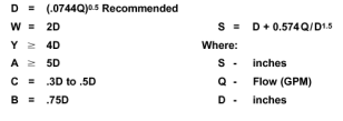
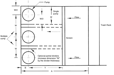
Dimension W is the width of an individual pump cell or the center-to-center distance of two pumps if no dividing wall is used.
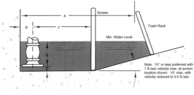
On multiple intake installations, the recommended dimensions in Figures 7 and 8 apply as noted above, and the following additional factors should be considered.
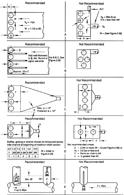
As shown in Fig. 10 (A), low velocity and straight in-line flow to all units simultaneously is a primary recommendation. Velocities In the sump should be approximately one foot per second, but velocities of two feet per second may prove satisfactory. This is particularly true when the design is based on a model study. Not recommended would be an abrupt change in the size of the inlet pipe to the sump or the inlet from one side introducing eddying.
In many cases, as shown in Fig. 10 (B), pumps operate satisfactorily without separating walls. if walls must be used for structural purposes or some pumps operate Intermittently, then the walls should extend from the rear wall approximately ten times the C dimension given in Fig. 7.

Fig. 7 Sump Dimensions

Fig. 8 Sump dimensions, Plain view, wet pit type pumps

Fig. 9 Sump dimensions, elevation view, wet pit type pumps

Fig. 10 Mulitple pump installations


